VISHAL BONDE

VOYAGER-II
Overview
Voyager — II is an interplanetary transport system concept designed to travel long distances in space. The designed has been simulated with the necessary animations to enable easy understanding. The design has been created in Autodesk Fusion 360.
BASIC FEATURES
•In-Flight Launch System
•Ion-propulsion Engine
•Life Support Systems
•Cargo Space
•Collect Fuel and Resource in space through ISS
•Capable of long Distance Travel
•Load Simulated and Verified Design

THE LAUNCH
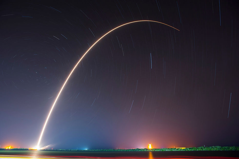
In-Flight Launch
We propose an In-Flight launch mechanism as it reduces the consumption of fuel drastically.The Space-Shuttle is launched along a tangential path once gaining enough momentum with the help of a conventional aircraft.

ENGINE
The Ion-Propulsion Engine
A key advantage of ion propulsion is efficiency. The exhaust from an ion engine travels up to 10 times faster than does the exhaust from a chemical engine, generating far more thrust per pound of propellant.
However, the thrust from an ion engine is very weak.This makes ion propulsion unsuitable for lifting spacecraft off the surface of Earth. In space, however, ion engines can run continuously for weeks, compared to minutes for chemical engines. These engines can build up significant thrust over time.
MECHANISM
The Mechanism in Detail :
•The Voyager II will leave the Earth's atmosphere housed inside the launched Space Shuttle.
•Once in Vacuum, the modules inside voyager will self assemble into the transportation system.
•The Life Support and Cargo modules attach by the sides of the voyager hence giving additional room inside.
•The empty space can be filled with fuel and food resources from ISS or preserved to bring back samples from other planets. •Once the resources are collected, the voyager is fully functional and ready to travel.
SIMULATIONS AND CALCULATIONS

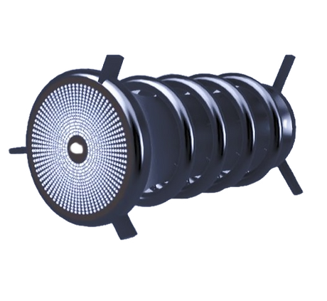
ION-PROPULSION CANNISTER
The various components have been subjected to relevant loads caused due to thrust and internal cabin pressure and the results obtained have been analyzed through the stresses that occur within. The actual Deformation has been taken into consideration.
INTERMEDIATE ATTACHMENT
•The average load on the thruster canister and the attach been incorporated into the simulations.
•The optimal internal cabin pressure is taken to be 100,00 shell structure. The various components have been thrust and internal cabin pressure and through the stresses that occur within.

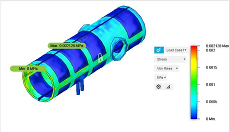
SHELL WITH CABIN PRESSURE
•High strength Aluminium Alloy offers the optimal toughness and stress resistance therefore incorporated in rnost of the components of the voyager.
•The transparent surfaces of the voyager such as the 360degree Glass pane is made up of Alumino- Silicate with a thickness of 250mm.
•Thrusters used for docking are made of Titanium Alloy.
Conclusion
Shuttle carrier aircraft developed by NASA has launched shuttles in 1977, 1982 and 1991 Endevor shuttle. Minimum stress acts along all the components as represented by the Blue zones in the simulations.Satellite docking systems have been used for more than 50 years since the first Apollo program.